Yayınlandı:
9 Nisan 2015
Kategori: Kataloglar
Alışveriş Sepeti
Şu anda ödeme için uygun ürününüz bulunmamaktadır.
Distribütör Seçimi
Alışveriş sepetiniz için kullanmak istediğiniz distribütörü seçin.
Distribütör

Eaton orta gerilim Power xpert UX katalogu
Eaton orta gerilim Power xpert UX katalogu, güvenli MV switchgear
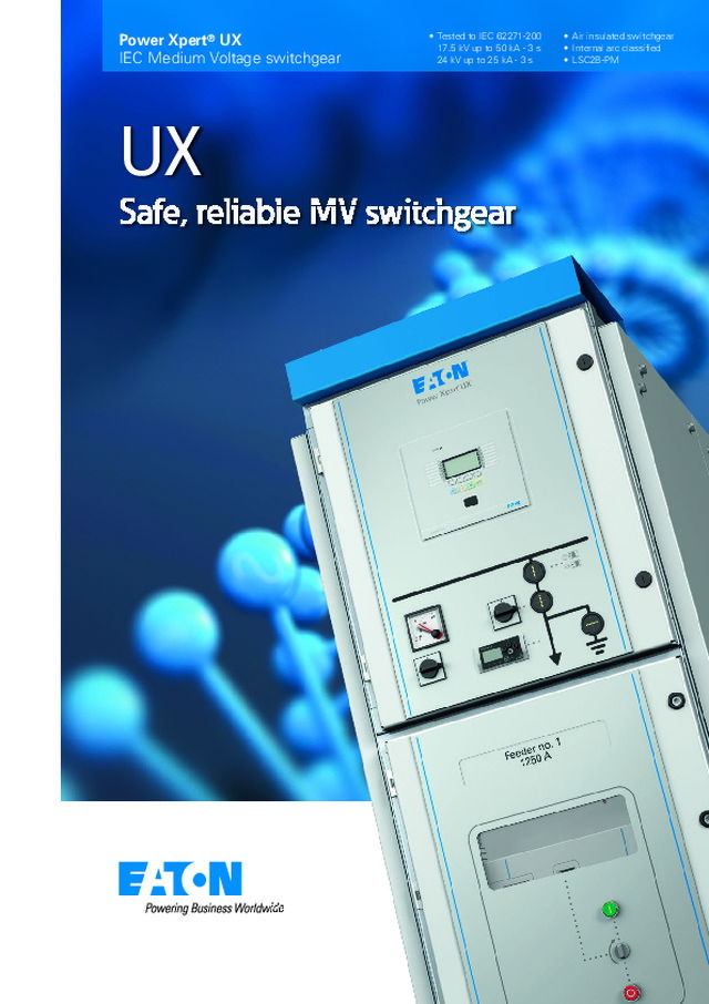
Power Xpert ® UX IEC Medium Voltage switchgear Safe, reliable MV switchgear UX • Air insulated switchgear• Internal arc classified• LSC2B-PM • Tested to IEC 62271-200 17.5 kV up to 50 kA - 3 s24 kV up to 25 kA - 3 s
Hydraulics Poweringbusinessworldwide Next generationtransportation Eaton is driving thedevelopment of newtechnologies – from hybriddrivetrains and emission controlsystems to advanced enginecomponents – that reduce fuelconsumption and emissions intrucks and cars. Higher expectations We continue to expand ouraerospace solutions andservices to meet the needs ofnew aviation platforms,including the high-flying light jetand very light jet markets. Building on our strengths Our hydraulics businesscombines localised service andsupport with an innovativeportfolio of fluid powersolutions to answer the needsof global infrastructure projects,including locks, canals anddams. Powering Greener Buildingsand Businesses Eaton’s Electrical Group is aleading provider of powerquality, distribution and controlsolutions that increase energyefficiency and improve powerquality, safety and reliability.Our solutions offer a growingportfolio of “green” productsand services, such as energyaudits and real-time energyconsumption monitoring.Eaton’s Uninterruptible PowerSupplies (UPS), variable-speeddrives and lighting controls helpconserve energy and increaseefficiency. Eaton delivers the power inside hundreds of products thatare answering the demands of today’s fast changing world. We help our customers worldwide manage the powerthey need for buildings, aircraft, trucks, cars, machineryand entire businesses. And we do it in a way thatconsumes fewer resources. Automotive Aerospace Electrical Truck Hydraulics Automotive Aerospace Electrical Truck Hydraulics 2
MV switchgear technology is in our DNA Eaton Corporation is a worldwide leader in the design, manufacture, and sale of safe, reliable and high-performance medium voltage power distribution equipment in accordance with IEC, GB and ANSI standards. Complete Global Medium Voltage Switchgear Solutions Eaton, a premier leader in designing and manufacturing powerdistribution and protection equipment in the electrical industry,offers a comprehensive range of medium voltage (MV) solutionsto meet the needs of virtually every application. From productsthat feature cutting-edge design that allow for easy access,maintenance and space savings, to arc-resistant products thatenhance safety, Eaton’s medium voltage solutions provide avariety of products for every need. Additionally, Eaton’s globalservice network provides maximum customer support in allregions of the world. As one of the few completely vertically integrated and diversifiedindustrial manufacturers in the world, Eaton designs not only MVassemblies, but also the key components that comprise the MVsolutions – from steel housing and circuit breaker compartmentsto vacuum interrupters, circuit breakers, bus systems and fuses. Eaton’s MV heritage, strengthened by acquisitions such asWestinghouse DCBU, Cutler Hammer, MEM and Holec, hasresulted in breakthrough MV technologies and numerousinternational patents over the years. Part of Eaton’s complete electrical PowerChain Solutions – which help businesses minimize risks while realizing greaterreliability, cost efficiencies, capital utilization and safety – Eaton’s medium voltage equipment meets all applicablestandards and certifications such as IEC, NEMA / ANSI, GB, UL, IEEE, KEMA and CSA. When it comes to medium voltage solutions, you can trust theone name with a long history of proven performance: Eaton. Eaton’s range of SF6 free switchgear for Medium Voltage 3
UX Safe, reliable MV switchgear with sustainability built-in Innovative in its design, originated from the Unitolefamily, field-proven over forty years of vacuum circuitbreaker production and fully third-party certified to IEC 62271-100 and IEC 62271-200, Eaton's new UX rangeof compact air insulated with drawable Medium Voltageswitchgear leads the industry in safety, reliability,performance and sustainability. Knowledge andunderstanding Eaton has over 80 yearsexperience in the design,manufacture and application ofMedium Voltage switchgear.Being at the forefront oftechnological advances, wepioneered the use of vacuumtechnology 80 years ago andintroduced epoxy-resin insulationover 50 years ago. Eaton is stillcommitted to developing, inno -vating and improving - as wellas to reducing size and costs. Millions of our vacuum inter -rupters have been in operationin every type of environment inthe world, catering for thewidest range of applications. It is this know ledge, under -standing and experience thatmake Eaton the logical choicefor the safe control and protec -tion of distribution systems. UX is particularly suited toprovide control and protec tionfor cables, transformers,capacitors and motors usedacross many industries. In factUX excels anywhere thatmedium voltage power has tobe switched, controlled andprotected. Built to the highest qualitystandards UX is designed and fully third-party type-tested to the latestIEC 62271-200 standards, withfull segregation by earthedmetal partitions of all the majorcompartments, and is equippedwith Eaton's very latest range ofIEC vacuum circuit breakerstype W-VAC i - which are fully third-party type-tested inaccordance with IEC 62271-100. Using Eaton's state of the arttechnology and manufactured inaccordance with the highestquality standards, our engineershave integrated coretechnologies, such as circuitbreaker and mechanism design,vacuum technology, solidinsulation and electrical fieldcontrol to build a reliable andcompact system, which benefitfrom the best practicesincorporated in our currentmedium voltage range. The system, which comprises acomplete range up to 4000 A,uses only environmentallyfriendly technology andmaterials. UX is based onvacuum technology and airinsulation, and is therefore theperfect alternative to environmentally harmful SF 6 gas insulated switchgear. It is also produced with fullyrecyclable materials ensuringthat at the end of its life theproduct can be safely andefficiently recycled - providing a wholly sustainable solution to medium voltage switchgearapplications. Some applications are: • Power distribution • Water and waste water treatment • Mining • Commercial buildings • Industrial facilities • Oil and gas (on- and off-shore) • Marine • Airports and hospitals. 4 A complete range of compact, environmentally-friendly switchgear up to 4000 A
Combining advanced technology with proven engineering excellence, the UX range provides thehighest safety and reliability standards withoutcompromising competitiveness. As pioneers in vacuum and arc-interruption technologies, furtherdeveloped over 40 years, Eaton has millions of vacuum interrupterssuccessfully operating in multiple applications worldwide; Eaton'slatest vacuum circuit breaker, the W-VAC i , sits at the heart of UX. 5 World leading technology with safety built in Low initial costs due to: • Compact footprint • Cable access from front or rear • Cable entry from either top or bottom • Easy-access cable compartment for ease ofcable connection • Integrated arc chamber • Back to wall configuration with front cable access Low lifetime cost The switchgear is type tested tothe latest IEC 62271-200 andhas third-party certification toprove internal arc containmentclassification of AFLR from 25 kA for 1 second and up to 40 kA for 1 second and 50 kAfor 0.5 second. This means there is minimal risk of harm topersonnel in the unlikely eventof an internal arc in the cablecompartment, vacuum circuitbreaker compartment or thebusbar compartment in anydirection: front, rear and sidesof the switchgear. Fully type-tested to latest IEC standards Increasing global legislationconcerning the use of green -house gases such as SF 6 gas and their related disposal costs,makes vacuum technology withits reliability, low maintenance,and low environmental impactthe choice for now and thefuture. As the world strives to reducethe amount of SF 6 gas used in all applications there is aresponsibility on the users ofelectrical switchgear to find,where appropriate, alternativesto SF 6 gas as an insulation and switching medium. Air and solidinsulation switchgear systemsincorporating vacuum switchingtechnologies are a reliable, safeand economic alternative foruse in electrical systems below36 kV and therefore should beused instead of SF 6 gas insulated systems. Modern medium voltageswitchgear employing vacuumtechnology together with airand epoxy resin insulationprovides: • Minimum number of parts and components • No special requirements for the end-of-life disposal of the switchgear • Environmentally-friendly materials used in the design • No use of SF 6 -gas for switching and insulation(green switching) • No risk of damaging leaks of SF 6 gas or of toxic by- products • Energy-efficient production and assembly, withenvironmentally friendlyenergy sources • Minimal number of transition points in the primary designenables low energy lossduring operation • Only re-usable and/or recyclable materials used Low environmentalimpact • Robust maintenance-free design with minimumnumber of parts • W-VAC i circuit breaker has a long life of 20,000 operationswithout the need for activemaintenance. • Advanced vacuum interrupter contact designsprevent hot spots, createless heat and minimiseelectrode erosion to yieldlonger life. • No SF 6 pressure checks and specialised refillingprocedures Low end of life disposal costsdue to: • Vacuum switching technology • Air insulation • Recycling or re-use of all materials possible • No special decommissioning procedures necessary Minimal costs duringservice due to: • Compartments are protected against penetration byobjects • Internal arc classification of AFLR provides operatorsafety in the unlikely eventof an internal arc • Operation only possible with the circuit breakercompartment door closed • Logical mechanical and electrical interlocks preventmal-operation • Capacitive voltage detection system for verification ofsafe isolation from supply • In the unlikely event of vacuum interrupter failurethere is no damage topersonnel and no harmfulgases are emitted. • Vacuum interrupter contact erosion is negligible • Fully encapsulated vacuum interrupters • Fewer moving parts in the pole unit versus other arcinterruption technologies Safety, reliability andperformance • Cable connection and user interfaces for operation onthe same side of the unit • Multiple cables per phase with standard compressionlug for ease of cableconnection • Secondary cable entry points on both sides of the lowvoltage compartment topplate • Secondary cable wire way runs complete over thelength of the switch gear tohelp with inter-unit wiring. • Secondary cable terminals positioned at a goodreachable height within thelow voltage compartment • Clear and simple, straightforward operationpanels combined with anactive mimic diagram User friendly • Complete design third party certified in accordance withIEC 62271-200 • Internal arc fault tested in accordance with IEC 62271- 200 • Quality assurance in accordance with ISO 9001 • Separate compartments for; cable, vacuum circuit breakerand busbars • Integrated arc chamber • Routine tested Reliable and safe inoperation
6 The integral arc-chamberevacuates the gassesassociated with an internal arc.Optional standard parts areavailable to extend the arcchamber; flanges and grilles areavailable to exhaust the gassesoutside the switchgear room. Arc chamber 1 The compartment issegregated with earthed metalpartitions and has ample spacefor control and protectiondevices. Low voltagecompartment 3 A fully segregated metal wire-way is mounted at the top ofeach switchgear panel thatconnects together to form acontinuous low voltage wire-way that runs along the entirelength of the switchgear. Low voltage wire-wayfor inter panel wiring 2 UX vacuum technology switchgear system Basic design UX is modular in construction, ensuring that any panelcombination and rating can be applied on a system. In addition, there is no limit to the number of panels that can beused in an installation, as several sections can easily be connectedtogether. Because the panels can be quickly assembled andconnected, flexible commissioning of the switchgear is an addedbenefit. 5 7 2 1 4 8 10 3 9 11 6
7 Fully segregated by earthedmetal partitions, with its ownpressure relief channel into thearc chamber, the compart mentprovides all the safetyinterlocking mechanismsrequired for safe and reliableoperation of the vacuum circuitbreaker. Manual operationbuttons allow for full operationof the vacuum circuit breakerfrom the front of theswitchgear with the door fullyclosed. The circuit breaker ismechanically interlocked withthe compartment door so thatthe door cannot be openeduntil the circuit breaker isswitched Off and racked outinto the Test position. Vacuum circuit breakercompartment 5 Busbars are totally enclosed intheir own earthed metalcompartment which vents intothe arc chamber. Fully insulatedalong their entire length, thebusbars are type tested forratings up to 4000 A, 50 kA for3 seconds. Epoxy mouldingssegregate switchgear sections. Busbar compartment 4 Individually operated automaticearthed metal shutters for boththe Line (busbar) and Load(cable) connections can bepadlocked in the closedposition. When the breaker is inTest or Disconnect positionsthe shutters automatically closeto prevent accidental contactwith any live parts. Automatic shutters 6 Cast resin CTs are provided asstandard in a wide range ofratings, with an option to uselow voltage tape-wound CTs inthe same location. Current transformers 8 Ample cable terminationprovision is provided up to 9single core cables per phase toenter the bottom of theswitchgear and are terminatedwith compression lugs ontocopper tails provided in thebottom of each panel. Cable terminations 10 An earth bar system is providedmaking connections to thestation earth easy andeffective. The earth bar systemhas been fault tested and runsvertically and horizontally withineach panel section and isconnected to the earth switch,when provided. Earth bar 11 The voltage transformers areavailable in 3 configurations:Fixed, Withdrawable withshutters, and Withdrawablewithout shutters. All options arefitted with withdrawable primaryfuses. The compartment doorcan be interlocked with theearth switch to ensure that thecables are safely earthed beforethe door is opened. The with -drawable option with shutterscan be disconnected from thesupply with the compartmentdoor closed and with cables stilllive. The door can then beopened to remove thetransformers safely. Voltage transformers 9 The earth switch is operatedfrom the front of theswitchgear, with mechanicalindicators to show the switchposition. A window allows directviewing of the earth switchposition. The earth switch ismechanically inter locked withthe circuit breaker or contactortruck such that it can only beclosed when truck is in theTest/Disconnect position. Thecircuit earth switch can bemechanically interlocked withthe cable compartment door asan additional safety measure. Circuit earth switch 7 superior safety, reliability and performance
Clear distinct operator panel for user friendly operation 8 Eaton has a range of preferredrelay options that can be fittedas standard. However, customerspecific protection relays fromany manufacturer can be fittedto the compartment door. Protection relay 2 Optional LED indication of earthswitch Open/Closed status. Earth switch indicator 8 The circuit breaker compartmentdoor viewing window providesvisual indication of the positionof the circuit breaker indicating: • The status of the breaker • The status of the spring- charged mechanism The cable compartment doorviewing window allows visualindication of: • The status of the earth switch • Inspection of the cable connections Viewing windows 9 Easy to understand mimicdiagram of each circuit. Mimic diagram 3 Breaker Open/Closed statusindicator. Breaker Open/Closed commandswitch. Optional LED indication ofspring charge mechanism"Charged" status Electrical operationwith circuit breakerstatus indicator 7 Clear to view panel with allcontrols and indications clearlyvisible and easy to operate. Low voltage controland protectioncompartment 1 Breaker position indicationshows the breaker in theConnected/Service orDisconnected/Test position. Circuit breakerposition indicator 6 Circuit breaker Open and Closebuttons Manual circuitbreaker operation 10 Circuit breaker racking In/Outmechanism Circuit breakerracking mechanism 11 Each circuit breaker panel canbe equipped with an optionalstandard three phase voltagedetection system for voltagedetection to IEC 61243-5. TheVDS is driven from a capacitivedivider fitted within theinsulators connected to thecable connection and showsthe operator if the connectedcable is live. Voltage detectionsystem 5 Option for an ammeter andphase selector switch. Option for voltmeter and phaseselector switch. Metering with phaseselector switch 4 Control and protection 1 6 7 8 4 2 9 9 3 5 10 11
9 Eaton core technologies Cast-resin is a high-qualityprimary insulation material. By using cast-resin for solidinsulation, Eaton's designengineers can shape the partsspecifically for optimalinsulation, robust constructionand cooling purposes. With over 50 years ofexperience in the design andmanufacture of cast-resincomponents, Eaton hasdetermined that the bestsolution is to embed theconductors and vacuuminterrupters directly into themoulding to form a singleencapsulated pole unit (EPU). Features • High mechanical strength for improved durability andmechanical life of the poleunit • Protected against adverse climatic conditions andhumidity • Protected against mechanical impact, shockand vibration • Provides high thermal conductivity for improvedtemperature rating • High electrical resistivity and creepage current resistancefor improved insulation andcompact design Solid insulation using cast-resin technology Eaton's vacuum interruptersconsist of a ceramic cylinderthat houses fixed and movablecontacts. Movement of thecontact under vacuumconditions is performed bybellows. A shield surroundingthe contacts prevents theinsulators from becomingcontaminated by any metalvapour produced during currentinterruption. This shield alsoensures good voltage potentialdistribution over the insulator. A special feature of Eaton'svacuum interrupters is thecreation of a large number ofparallel arcs between thecontacts. This "diffusedischarge" is characterised byvery low arc voltage and short arc times, resulting in very low arc energy - so contactwear in a vacuum interrupter is negligible. Vacuum interrupters are main -tenance free and are certifiedup to 30,000 operation cycles. Vacuum technology: safe, compact and reliable 1. Bellows 2. Bellows shield 3. Ceramic insulators 4. Movable contact 5. Magnetic laminations 2 4 5 3 1
10 The busbar system is constructed from high-quality hard drawncopper bars of standardised cross-section. Features • Busbar compartment runs over the entire length of the switchboard • Individual panel segregation between sections of the busbar chamber • Constructed from high-quality hard-drawn copper of standard dimensions • Fully insulated over the entire length of the switchboard • Busbar chamber vents directly into the integral arc-chamber • Busbar ratings up to 4000 A • Busbar short circuit ratings up to 50 kA - 3 s Busbars The vacuum circuit breaker uses a simple and reliable, true twostep spring charged mechanism for operation of the vacuuminterrupters. The construction of the mechanical linkage betweenthe actuator and the drive rod of each of the three vacuuminterrupters is simple and effective. Features • Environmentally friendly vacuum interrupters totally encap - sulated within pole units constructed of solid epoxy resin • Mechanically and electrically trip-free stored energy mechanism design • Integrated mechanical lever for manual charging operation with pushbutton control • Spring charged indicator with contacts for remote indication of spring status • Mechanical status indicator for Open/Closed • Auxiliary contacts for Open/Closed position • Position indicator for Connected/Test position within the compartment • Auxiliary contacts for remote position indication • Mechanically interlocked with the compartment door • Mechanical interlock to ensure the breaker is in the open position before it can be racked-in or racked-out Main components Vacuum circuit breaker
11 For motor starters, transformers and capacitor banks, the UX system is available with vacuum contactor trucks. Contactors for 3.6 or 7.2 kV can be mounted on a truck together with fuses, andvoltage transformers. Surge arresters can also be mounted at thecable terminals. For motor control applications up to 7.2 kV, UXincorporates the Eaton range of SL contactors. For motor startersat 12 kV please contact Eaton. Features • Environmentally friendly vacuum interrupters • Ratings up to 400 amps at 6.6 kV • Capacitor switching up to 295 amps at 6.6 kV • Maximum interruption current of 8.5 kA • Fuse protected up to 50 kA • Electronic coil control for optimum control of the coil voltage and reduced watts loss means more efficient use of powerand lower heat generation • Electronic coil control allows for field selectable control voltages and drop out times • Up to 6 auxiliary contacts in any combination of Normally Open and Normally Closed configurations • Mechanical latch option is available with electrical unlatch signal. • Long life with up to 1 million electrical operations and 2.5 million mechanical operations with no maintenance oradjustment required Contactor All panels can be equipped with a cable earthing switch. The earthswitch is mechanically interlocked with the circuit breaker so thatthe earth switch can only be operated when the circuit breaker isopen, and withdrawn to the 'Disconnected/Test' position. Features • Fully fault-rated earth switch • Operated from the front of the panel • Auxiliary contacts for service/earthed positions • Mechanical position indicators • Mechanically and/or electrically interlocked with the vacuum circuit breaker Earth switch
12 Safe and reliable in use IEC62271-200 describes theextent to which the switchgearand control gear are allowed toremain operational in caseaccess to a main compartmentis necessary. UX has the highest attainablelevel of Loss of ServiceContinuity of LSC2B. Category LSC2B This form allows for maximumcontinuity of service of thesystem during access to thecompartments inside theswitchgear - meaning that themain switching device of eachfunctional unit of an LSC2Bswitchgear is fitted in its ownaccessible compartment.Maintenance may be performedon the main switching devicewithout de-energizing the corresponding cable connectionor the main busbars. As aconsequence, in this exampleof LSC2B switchgear, aminimum of 3 compartmentsfor each functional unit isnecessary: • 1 for each main switching device • 1 for components connected to one side of a mainswitching device, forexample, feeder circuit • 1 for components connected to the other side of the mainswitching device, forexample, busbars Switchgear is classified asLSC2B when it is possible andsafe to open the circuit breakercompartment when the cableand busbars are energised. In addition to the IAC and theLSC classifications, IEC62271-200 defines the type ofpartitions required betweeneach panel and between eachfunctional unit within the panel. UX employs only earthed metalpartitions and therefore has thehighest level of partitionclassification of PM. UX switchgear is equipped withautomatic earthed metalshutters. Individually operatedshutters for both the Line (busbar) and Load (cable)connections can be padlockedin the closed position. Whenthe vacuum circuit breaker is inthe test or the disconnectpositions the shutters willautomatically close to preventaccidental contact with any liveparts. For testing purposes,special shutter lifters are usedto maintain the shutters in theopen position. Colour codedand labelled 'Busbar' and'Cable', the shutters are easilyidentified as Open or Closed. Loss of service continuity classification Partition classification Internal Arc Classification (IAC) of AFLR While the integrity of theequipment to provide continuityof supply was a major designconsideration throughout itsdevelopment, the safety of theoperator has also been one ofthe most important criteria, witha number of reassuring featuresbuilt in. All of Eaton's medium voltagesystems, including UX, havebeen third party tested to allrelevant standards, and are inaccordance with IEC regulations. Eaton has always emphasisedthe need to design and createsafe switchgear for operators atall times. One of the biggest potentialthreats to operators is an internal arc in the switchgear.The metal-clad design and therobust construction has enabledUX to success fully pass internalarcing test in accor dance withIEC 62271-200 in all threeprimary compart ments andprovides an IAC rating of up to40 kA for 1 second and 50 kAfor 0.5 second. IEC62271-200 defines the levelof protection to be provided inthe event of an internal arc faultbeing generated within theswitchgear. UX has been provenby independent third-party testto provide an IAC Classificationof IAC = AFLR. A = Protection for personnel F = Protection at the Front of the switchgear L = Protection at the Lateral (sides) of the switchgear R = Protection at the Rear of the switchgear The IEC standard requires thatan internal arc test is carried outin each of the power sections ofthe switchgear. In UX thismeans the cable compart ment,the vacuum circuit breakercompartment, and the mainbusbar compartment. The standard allows for eachtest to be conducted inindividual switchgear panels -meaning that three separatepanels can be used to prove theintegrity of the design. UX, however, has achievedIEC62271-200 with all threetests being conducted in thesame panel. It is an importantsafety feature and indication ofstrength that UX passed allthree required tests in the samepanel. The UX has the following IACratings: 12 kV and 17.5 kV: 25 kA - 1 s, 26.3 kA - 1 s, 31.5 kA - 1 s, 40 kA - 1 s and 50 kA - 0.5 s 24 kV: 25 kA - 1 s Proven experience and knowledge gained by Eatonover many years in the areas of cast-resin technology,vacuum technology, arc interruption and electricalfield control have been integrated in the design anddevelopment of UX - ensuring that the switchgear issafe and has high operational reliability throughout itslifetime.
UX has an external protectiondegree of IP4X as per IEC 60529with an option of IP41 available.Internal ingress protection toIP2X is standard with an optionfor IP3X for more demandingapplications. Separationeliminates the penetration offoreign objects and reduces therisk of accidental contact withany live parts. Ingress of foreign objects 13 For personnel safety UX is designed with anumber of comprehensive mechanical interlocksto prevent unsafe operation. • It is not possible to rack-in or rack-out a circuit breaker unless it is in the Off or Open position. • It is not possible to close a circuit breaker unless the circuit breaker is in the Connectedor Test position. • The secondary socket can only be disconnected with the circuit breaker in thetest position. • Closing the circuit breaker is only possible with the secondary contacts connected. • It is not possible to close the earth switch when the circuit breaker is in the Connectedposition. • The door of the vacuum circuit breaker compartment can only be opened when thecircuit beaker is in the Disconnected / Testposition. • It is only possible to rack-in or rack-out the circuit breaker when the circuit breaker door is closed. • The cable compartment door can only be opened when the earth switch is in the Closed position. • The earth switch cannot be Opened when the cable compartment door is open. Safety interlocks In addition to the third partycertified type testingprogramme to prove theintegrity of the UX design,Eaton conducts routine testson each vacuum interrupter,circuit breaker and switchgearpanel. At a minimum thesetests confirm compliance withthe relevant IEC standards;however customer specific testprocedures and witness oftests can be accommodated.To ensure quality, all processesare performed in accordancewith ISO 9001 - at every stageof production the components,circuit breakers and currenttransformers are inspected forcorrect functioning. When theentire installation has beenassembled, a thorough visualinspection is carried out,together with the requiredmechanical, functional andelectrical checks. Routine tests IEC62271-200 defines theaccessibility classification foreach of the power sections inthe switchgear. UX has thefollowing accessibilitydefinitions. • Busbar: tool-based/non-accessible • Circuit breaker: interlocked controlled • Cable: tool-based or option forinterlocked controlled Accessibility ofcompartments
14 The UX is designed to be environmentallyfriendly throughout thelife-cycle: from production,during service and at theend-of-life. One of Eaton's key strategicinitiatives is to provideenvironmentally friendlyproducts. This requiresexamination of the total life-cycle, from design todecommissioning. The product life-cycle can bedivided into five main blocks.These blocks are • The design • Materials used • The assembly • The operational phase • The decommissioning Eaton's production plants actentirely in accordance with therules and procedures of the ISO 14001 environmentalcertificate during developmentand production processes. Environmentally friendly Sustainability Material selection and thenumber of parts that are usedto manufacture the UX arecritical to determining howenvironmentally friendly themanufacturing process is. Eaton selects its materials toensure that they have the lowest possible impact on theenvironment. It is essential thatthey are equally safe for people- not just during use, but at theend of service life too. Within UX and the W-VAC i circuit breaker, a combination ofsolid (cast-resin) and air is used as insulation. The cast-resintechnology, in combination withelectrical field calculations,provides a very compact,environmentally friendly designfor the circuit breaker and theswitchgear. Because theswitching medium - vacuum - is used, UX can be completelyrecycled at the end of its lifewithout any issues relating tosafety procedures, specialhandling or safe disposal. Environmentally friendly design From the very beginning Eatonmade a fundamental choice notto use SF 6 as a switching and insulation medium for mediumvoltage equipment - it is on thelist of greenhouse gasses in theKyoto protocol and is the mostpotent of the six maingreenhouse gasses, with aGlobal Warming Potential(GWP) of 23,000. Some medium voltageswitchgear systems use SF 6 gas as the insulating medium. Leakage of SF 6 gas from switchgear contributessignificantly to the threat of thegreenhouse effect andassociated climate change.They also require additionalsafety measures and specialhandling requirements at theend of life. No use of SF 6 -gas for insulation or switching UX is produced in an energyefficient environment. Standardprocesses and materials areused in the design and requireno special handling or manu -facturing processes, thusreducing the amount of energyrequired to manufacture andassemble the switchgear. Energy efficient assembly Besides the energy sources,special focus is placed on theefficient use of material duringassembly. For example by usingadvanced nesting tools thesheet steel plates are cut withthe least amount of waste, andsimilar principles are followed inthe design and manufacture ofother product components. Efficient use of materials UX is designed for a lifetime ofat least 30 years; therefore theenergy usage for maintenanceactivities during this long periodis minimal. Due to the greeninsulation and switching tech -nology, there is also no leakageof the harmful SF 6 gas during its lifetime and no need forperforming extra mainte nanceactivities on SF 6 gas pressure checks. Minimum service checks on site All materials within UX can bere-used or recycled. Becausethe UX uses no SF 6 gas, there is no possibility of leakage ofthis greenhouse gas duringdecommissioning theswitchgear. Re-use or recycling ofmaterials The number of electricalcontact or changeover pointswithin the UX system has beenkept to an absolute minimum.This reduces the potentialnumber of "hot spots" andprevents additional energy lossassociated with contactsurfaces. Minimal energy loss during operation
Low total cost ofownership Designed to provide at least 30 years of reliable servicethe UX design guarantees low overall cost of ownershipwhen considered over the lifetime of the switchgear. Life-time costs can be split into initial costs, costs incurred duringservice and finally, costs for disposal of the switchgear. All costsof ownership are influenced by different features of theswitchgear provided with no concession to quality and reliability. 15 Panel dimensions With panel dimensions of 600 mm, 800 mm and 1000 mm with only 3 depths of panel across all ratings of1320 mm, 1500 mm and 1550 mm, UX is one of themost compact designs of airinsulated medium voltageswitchgear available today. Thecompact design of UX allowsfor smaller switchrooms to bebuild further reducing theoverall cost of installation. Flexible cable access The UX offers top and bottomcable entry with cable accessfrom either front or rear. If frontaccess is chosen it is possibleto mount the UX panels flushagainst the wall thus reducingfurther the space needed in thebuilding. Low initial costs UX switchgear has a typicallifetime of at least 30 years.Depending on the location ofthe installation, this lifetime canbe extended. If, for any reason,a decision is made not to usethe switchgear any further itcan be fully recycled. When decommissioned, theswitchgear can be dismantledand the different materials caneither be re-used or recycledwith total safety. Because noSF 6 gas is used, decommis - sioning is a less complicated,more cost effective and anenvironmentally friendlyoperation. There are no specialprecautions, tools ordecommissioning methodsrequired. Low disposal cost Costs during service ofswitchgear can accumulate dueto damaged parts requiringreplacement, or by maintenancecycles set up for critical partsthat will not reach theirexpected lifetime without beingserviced. Keeping this in mind during the initial design of the UX, thefirst design steps undertakenwere to: • Minimise the number of parts used in theconstruction • Design using industry standard or readily availableraw materials • Prevent internal parts from being damaged during thelifetime of the unit. This robust construction, usingonly the minimum number ofparts, is based on our longexperience of buildingswitchgear. During productionof the panels, routine tests arecarried out by specialists, toensure that the panels achievethe quality that they aredesigned for. Low cost during service By designing a simple, modular,efficient, proven, low energyspring charged mechanismwith the fewest possiblenumber of parts for the vacuumcircuit breaker, the maintenancerequirements normallyassociated with this type ofmechanism is dramaticallyreduced. With proven reliability of up to20,000 operations the UniversalMechanism Assembly used inthe W-VAC i breaker helps to provide a virtually maintenance-free circuit breaker. Vacuum interrupter designplays an important role in thereduction of maintenance.Eaton's vacuum interruptersemploy a 'diffuse discharge'design which practicallyeliminates contact wear.Coupled with the proven solidinsulation technology Eatonemploys in the manufacture ofthe encapsulated pole unit, theW-VAC i range of vacuum circuit breakers is considered virtuallymaintenance free. Switchgear that uses SF 6 gas as an insulation medium has aninherent leakage rate. Tomaintain an adequate insulationlevel within this type ofswitchgear, the pressure of theSF 6 gas present in the switchgear tanks must bechecked and refilled on aregular basis during the unit'slifetime. With UX the extra costsinvolved in checking and main -taining the required insulationlevel are not incurred. Thecombination of vacuum inter -rupters for switching, cast-resintechnology and clean air as theinsulation medium, is environ -mentally friendly and maintainsthe same quality level duringthe complete lifetime of UX. Bynot using SF 6 gas in UX, an owner is also not faced withthe admini stration costsinvolved in registering thenumber of kilograms of SF 6 gas in the installation. Minimal inspection
16 Standards UX complies with the following international standardsIEC 62271-1 Common specifications IEC 62271-100 Circuit breakers (E2, M2, C2) IEC 62271-102 Disconnectors and earthing switches (E2, M0) IEC 62271-200 Metal enclosed switchgear and controlgear IEC 60044-1 Current transformers IEC 60044-2 Voltage transformers IEC 60529 Degrees of protection (IP Code) IEC 61850 Communication networks and systems in substations IEC 61243-5 Live working - voltage detectors - Part 5: voltage detecting systems Flexibility in design Every application of thistype of system is unique,so Eaton offers a widerange of different paneltypes and field versions. If, in due course, additionalcapacity in the form of morepanels is required, UX caneasily be extended to the rightor left with only minimaldisruption to the supply forfinal connection of the busbars. Eaton realises that customersoften have their ownrequirements with respect tothe use of protection andcontrol components withinswitchgear, so the need forspecific components was takeninto account during productdevelopment and resulted in abasic primary design thatenables customers to integratesecondary protection andcontrol components accordingto their own specificationrequirements. Range of voltagetransformers All UX panels can be fitted with cast-resin insulatedvoltage transformers, of therequested transformer ratioand class, for voltagemeasurement on the cableside, or on the busbar side. The standard configuration isfor a fixed voltage transformerwith withdrawable fuses -although an option for truckmounted withdrawable voltagetransformers is also available. Range of currenttransformers In order to provide protectionand metering, the cast-resininsulated current transformersare housed in the fixed sectionnear the feeder cable terminals.All common transformer ratios,outputs, rated currents andclasses are possible. For highercurrent ratings above 2500 Acast-resin ring-type currenttransformers are used. It is also possible, as an option,to fit low voltages wire-woundcurrent transformers onto ascreened primary conductorinstead of the standard cast-resin block or ring typetransformers. Smart Grids and substationautomation Equipment for remotecommunication betweenpanels or automation systemscan also be installed in the lowvoltage compartment, makingthe system the perfect solutionfor current and future SmartGrid applications. Protection and controlequipment The protection and controlequipment is located in acompletely separate lowvoltage compartment with itsown access door. There isspace on the door for a mimicdiagram and for mountingequipment such as protectionrelays, voltage detectionsystems, meters, etc. In case additional space isrequired, the low voltagecompartment can be extended.
17 Electrical Data System 12 kV 17.5 kV 24 kV Rated voltage kV 12 17.5 24 Lightning impulse withstand voltage kV 75 95 125 Power frequency withstand voltage kV 28 38 50 Rated frequency Hz 50/60 50/60 50/60 Internal arc class AFLR Loss of service continuity category LSC2B Partition class PM Earthing circuit kA - s 25 - 3; 26.3 - 3; 31.5 - 3; 40 - 3; 50 - 1 20 - 3; 25 - 3 Accessibility of compartmentsCircuit breaker compartment Interlock-controlled Busbar compartment Tool-based/non-accessible Cable compartment Tool-based or Interlock-controlled External degree of protection IP4X (IP41 as an option) Internal degree of protection IP2X (IP3X as an option) Installation Indoor Temperature classification °C -5 to +40 Relative humidity (max) % 95 Busbar systemRated normal current A 1250, 1600, 2000, 2500, 3150, 4000 (FC [1] ) 1250, 2000, 2500 Rated short-time withstand current kA - 3 s 25 / 26.3 / 31.5 / 40 / 50 20 / 25 Rated peak withstand current kA/50 Hz 63 / 66 / 80 / 100 / 125 63 / 80 kA/60 Hz 65 / / 82 / 104 / 130 65 / 82 Circuit breaker ratingsRated normal current A 630, 1250, 2000, 2500, 3150, 4000 (FC [1] ) 800, 1250, 2000, 2500 Rated short-circuit breaking current kA 26.3 / 31.5 / 40 / 50 20 / 25 Rated short-circuit making current kA 65 / 82 / 104 / 130 65 / 82 Rated short-time withstand current kA - 3 s 26.3 / 31.5 / 40 / 50 20 / 25 Single capacitor bank switching C2 A 400 Multiple capacitor bank switching back to back C1 A 400 Class S1, E2 Auxiliary voltage V 110/120/127 Vac 50/60Hz, 208/220/240 Vac 50/60Hz, 24/48/60 Vdc, 110/125 Vdc, 220/250 Vdc MechanismRated operating sequence A O - 0.3s - CO - 15s - CO [2] O - 0.3s - CO - 180s - CO [3] Class M2 Number of operations up to 20,000 Number of operations interrupter up to 20,000 [1] FC = Fan cooled.[2] Operating sequence O - 0.3s - CO - 15s - CO is available on circuit breakers rated 12, 17.5 kV up to 40 kA and up to 2000 A.[3] Operating sequence O - 0.3s - CO - 180s - CO is available on ALL circuit breakers rated 12 and 17.5 kV and 50 kA, and all 12 and 17,5 kV circuit breakers rated ≥ 2500 A.
600 800 1000 A B 18 Dimensions (mm) Panel width 600 mm 800 mm 1000 mm 12 kV and 17.5 kV Max. rating 630 A / 1250 A 2000 A 3150 A / 4000 A (FC) Depth 1310 1310 / 1490 1490 Height (A) 2200 2200 2200 Height including arc chamber (B) 2760 2760 2760 24 kV Max. rating 800 A / 1250 A 2000 A / 2500 A Depth 1570 1570 Height (A) 2320 2320 Height including arc chamber (B) 2870 2870 ) 1500 mm for IAC classification ratings of 40 kA - 1 s and 50 kA - 0.5 s only. Weights (kg) Circuit breaker panel Max weight including circuit breaker 12 kV and 17.5 kV UX17 25 kA 630 A 600 mm wide 860 UX17 31.5 kA 1250 A 600 mm wide 880 UX17 40 kA 2000 A 800 mm wide 1200 UX17 50 kA 2000 A 800 mm wide 1230 UX17 40 kA 3150 A 1000 mm wide 1650 UX17 50 kA 3150 A 1000 mm wide 1650 24 kV UX24 20 kA 800A 800 mm wide 1460 UX24 25 kA 1250 A 800 mm wide 1480 UX24 25 kA 2000 A 1000 mm wide 1820 UX24 25 kA 2500 A 1000 mm wide 1820
The UX product range isvery flexible and has avariety of circuit optionsthat enable almost alltypes of application to be configured. The truck design is common forall the types enabling thereconfiguration of the panelwhile in service. For added configurationflexibility the Riser Panels canbe fitted on either the left orthe right side of theSectionaliser Panels. Also thewidth of the combination of Sectionaliser and Riser Panelsis kept to a minimum. Further flexibility is provided bythe Equipped Riser Paneloption. In this configuration anystandard equipment truck canbe fitted into the EquippedRiser, offering options forbusbar metering, earthing, anda disconnect truck. A wide range of additionaloptions are also available formounting within the mainprimary compartments. Thelow voltage control andprotection compartment alsooffers many options for controland indication. Product range Panel configurations Cell Cell VCB Panel Cell Contactor Panel Sectionaliser Panel Auxiliary Panel Cicuit Breaker Contactor Withdrawable VT Withdrawable VT Fixed VT Withdrawable Fuses Cell Cell Sectionaliser Panel Riser Panel Left Riser Panel Right Cell Busbar Earthing Cell Disconnector Cell Cell Cell Sectionaliser Panel Cell Sectionaliser Panel Cell Equipped Riser Left Cell Equipped Riser Right Cell Truck configurations 19
Eaton Industries (Netherlands) B.V.P.O. Box 237550 AA HengeloThe Netherlands Tel.: +31 (0)74 - 246 40 10Fax: +31 (0)74 - 246 40 25holec-info@eaton.comwww.eatonelectric.com © 2012 Eaton CorporationAll rights reserved. Form No. PG02200001U-v3 / 6057952May 2012 The information provided in this documentreflects the general characteristics of thereferenced products at the time of issue andmay not reflect their future characteristics.Eaton Corporation reserves the right tomodify the contents of this document andthe characteristics of the referencedproducts without prior notification. Eaton Corporation does not assume liabilityfor potential errors or omission of information in this document. Eaton’s Electrical Sector is aglobal leader in powerdistribution, power quality,control and automation, andmonitoring products. Whencombined with Eaton’s full-scaleengineering services, theseproducts provide customer -driven PowerChain™ solutionsto serve the power systemneeds of the data center,industrial, institutional, publicsector, utility, commercial,residential, IT, mission critical,alternative energy and OEMmarkets worldwide. PowerChain™ solutions helpenterprises achieve sustainableand competitive advantagesthrough proactive managementof the power system as astrategic, integrated assetthroughout its life cycle,resulting in enhanced safety,greater reliability and energyefficiency. For more information,visit www.eaton.com/electrical. Eaton medium voltage products in the energy chain Commercial buildings Offshore andmarine Distributionsubstations Processindustry Heavy industry Power generation Residentialapplications Shops andoffices Green energy Green energy Solutions andServices Transformerstations Industry Infrastructure 2 3 4 5 6 2 3 4 5 6 3 4 3 4 2 3 4 5 6 1 2 3 4 5 6 1 2 1 2 3 3 1 2 5 6 5 6 4 5 6 4 5 4 5 1 2 Power plants Mining Mainstations Power Xpert ® UX 5 MMS 6 Power Xpert ® FMX 4 SVS 3 Xiria 2 Magnefix 1